CHINESE
 ENGLISH

Products >> Canted Coil Spring
Product Introducion of ESINLINK's Canted Coil Springs
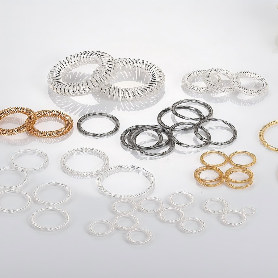
Table of Contents
1. Product Overview
2. Core Features
3. Materials & Plating
3.1 Base Materials
3.2 Plating Options
4. Specifications & Dimensions
4.1 Core Parameter Range
4.2 Standard Series Reference
4.3 Customization Instructions
5. Mounting Configurations & Orientation Design
5.1 Mounting Configurations
5.2 Orientation Design
6. Performance Parameters
6.1 Electrical Performance
6.2 Mechanical Performance
7. Application Fields
8. Customization Services
1. Product Overview
The canted coil springs supplied by GUANGZHOU ESINLINK INDUSTRIAL CO., LTD integrate internationally advanced manufacturing processes and core technologies. They are high-performance contact components that combine three functions: mechanical connection, electrical conduction, and EMI/RFI shielding.
With the multi-point contact design of independent coils, the products deliver stable and reliable connection in both static and dynamic electrical applications. Even under severe working conditions such as shock and vibration, they still ensure consistent conductive and grounding performance. Their compact structural design enables the management of high, medium and low grade currents in a smaller space with excellent temperature rise control. It can effectively reduce the size, weight and system complexity of equipment, providing an ideal solution for designers pursuing performance upgrading. Our canted coil springs are widely suitable for high-end application requirements in global industries such as industry, energy, medical care, aerospace and so on.
2. Core Features
2.1 Near-constant elastic force output: Exerts a near-constant force within the working deflection range, and the force value remains stable under extreme temperature changes. Far superior to the linear force characteristics of traditional helical springs, it ensures uniform contact pressure during the connection process.
2.2 Multi-point contact protection: Independent coils form multiple contact points, which greatly improve the reliability of conduction and grounding. Even in violent vibration or shock environments, it can maintain low and stable contact resistance to avoid connection interruption.
2.3 Excellent deformation resistance: Boasts excellent resistance to compression set, and can still maintain the original structure and performance after long-term use. Its service life is far higher than the industry average, reducing the frequency and cost of equipment maintenance.
2.4 Precision tolerance compensation: The unique coil design can automatically compensate for component misalignment, dimensional tolerance changes and mating surface irregularities, reducing assembly difficulty and improving the stability of the overall system.
2.5 High-efficiency heat dissipation & low temperature rise: Optimized structural design and high-quality material selection ensure minimal temperature rise (the maximum temperature rise of some models ≤ 30K) in high-current transmission scenarios, avoiding equipment performance degradation caused by overheating.
2.6 Multi-functional integrated design: A single component realizes three functions simultaneously: mechanical latching/locking, electrical conduction/grounding, and EMI/RFI shielding, reducing the number of parts required for equipment and simplifying system design.
2.7 Extreme environment adaptability: Through material selection and special plating treatment, the products can withstand harsh environments such as humidity, corrosion, high and low temperatures, and are suitable for a wide operating temperature range from -40℃ to +140℃.
3. Materials & Plating
3.1 Base Materials
3.1.1 Stainless Steel Series: 302, 316 and 316L stainless steel, with excellent mechanical strength and corrosion resistance. It delivers better force-per-unit compression performance than copper alloys for springs of the same size.
3.1.2 Copper Alloy Series: Beryllium copper alloy, zirconium copper alloy, high-conductivity beryllium bronze, high-strength beryllium bronze and chrome-zirconium copper. Among them, high-conductivity beryllium bronze has both excellent electrical conductivity and elasticity, making it the preferred material for balancing spring function and conductive requirements.
3.1.3 Special Alloys: Hastelloy C-276, Inconel X750, etc., suitable for special working conditions such as high temperature and strong corrosion.
3.2 Plating Options
3.2.1 Gold Plating: Provides excellent electrical conductivity, corrosion resistance and low contact resistance, suitable for high-precision, high-reliability electronic equipment and harsh environment applications.
3.2.2 Silver Plating: The first choice for high conductivity performance, which can meet the demand of high-current transmission. A protective coating is additionally applied on the surface to improve corrosion resistance, complying with international specifications such as MIL standards.
3.2.3 Nickel Plating: Balances corrosion resistance and cost, improves the surface hardness of the spring and extends its service life.
3.2.4 Tin Plating: Enhances electrical conductivity and oxidation resistance, reduces contact resistance, and is suitable for conventional electrical connection scenarios.
4. Specifications & Dimensions
4.1 Core Parameter Range
4.1.1 Wire Diameter: 0.08mm - 1.8mm (0.10mm - 1.5mm for standard range), customized wire diameters are available to match light, medium and heavy load application requirements.
4.1.2 Welded Ring Inside Diameter: Minimum 0.51mm (0.020 inch), maximum can be customized according to customer requirements.
4.1.3 Coil Dimensions: Coil width 0.4mm - 20mm, coil height 1.2mm - 4.6mm, which can be precisely matched to different groove design requirements.
4.1.4 Load Grades: Four grades including Light (L), Medium (M), Medium-Heavy (MH) and Heavy (H), suitable for working conditions with different force requirements.
4.2 Standard Series Reference
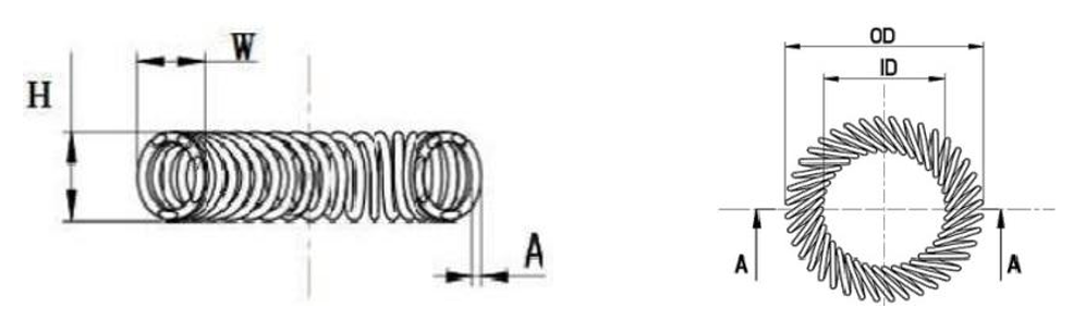
| P/N | Wire Diame(A) (mm) | Ref. Wide (W) (mm) | Ref. Height(H) (mm) | Inside Diame(ID) (mm) | Ouside Diame(OD) (mm) |
| ESIN-0140-0012-022 | 0.12 | 0.80 | 1.20 | 1.40 | 3.00 |
| ESIN-0238-0015-028 | 0.15 | 0.85 | 1.20 | 2.40 | 4.10 |
| ESIN-0300-0015-034 | 0.15 | 0.90 | 1.20 | 3.00 | 4.80 |
| ESIN-0300-0015-036 | 0.15 | 1.20 | 1.40 | 3.00 | 5.40 |
| ESIN-0360-0015-042 | 0.15 | 1.20 | 1.40 | 3.60 | 6.00 |
| ESIN-0400-0015-046 | 0.15 | 1.20 | 1.40 | 4.00 | 6.40 |
| ESIN-0500-0015-056 | 0.15 | 1.20 | 1.40 | 5.00 | 7.40 |
| ESIN-0600-0020-053 | 0.20 | 1.60 | 1.80 | 6.00 | 9.20 |
| ESIN-0800-0015-082 | 0.15 | 1.20 | 1.40 | 8.00 | 10.40 |
| ESIN-0800-0020-068 | 0.20 | 1.60 | 1.80 | 8.80 | 11.20 |
| ESIN-0800-0025-057 | 0.25 | 2.00 | 2.30 | 8.00 | 12.00 |
| ESIN-0800-0030-055 | 0.30 | 1.85 | 2.05 | 8.00 | 11.70 |
| ESIN-0900-0020-075 | 0.20 | 1.60 | 1.80 | 9.10 | 12.30 |
| ESIN-1000-0020-080 | 0.20 | 1.60 | 1.80 | 10.00 | 13.20 |
| ESIN-1000-0025-068 | 0.25 | 2.00 | 2.20 | 10.00 | 14.00 |
| ESIN-1000-0030-060 | 0.30 | 2.40 | 2.70 | 10.00 | 14.80 |
| ESIN-1100-0025-074 | 0.25 | 2.00 | 2.30 | 11.00 | 15.00 |
| ESIN-1200-0020-095 | 0.20 | 1.60 | 1.80 | 12.00 | 15.20 |
| ESIN-1200-0025-080 | 0.25 | 2.00 | 2.20 | 12.00 | 16.00 |
| ESIN-1200-0030-055 | 0.30 | 1.85 | 2.05 | 12.00 | 11.70 |
| ESIN-1200-0030-070 | 0.30 | 2.40 | 2.70 | 12.00 | 16.80 |
| ESIN-1200-0050-048 | 0.50 | 4.00 | 4.60 | 12.00 | 20.00 |
| ESIN-1400-0025-092 | 0.25 | 2.00 | 2.20 | 14.00 | 18.00 |
| ESIN-1400-0030-070 | 0.30 | 2.00 | 2.40 | 14.00 | 18.00 |
| ESIN-1400-0030-079 | 0.30 | 2.40 | 2.70 | 14.00 | 18.80 |
| ESIN-1500-0030-084 | 0.30 | 2.40 | 2.70 | 15.00 | 19.80 |
| ESIN-1600-0030-090 | 0.30 | 2.40 | 2.70 | 16.00 | 20.80 |
| ESIN-1700-0030-094 | 0.30 | 2.40 | 2.70 | 17.00 | 21.80 |
| ESIN-1800-0030-098 | 0.30 | 2.40 | 2.70 | 18.00 | 22.80 |
| ESIN-2000-0030-108 | 0.30 | 2.40 | 2.70 | 20.00 | 24.80 |
| ESIN-2200-0030-118 | 0.30 | 2.40 | 2.70 | 22.00 | 26.80 |
4.3 Customization Instructions
There are no fixed standard sizes for our products. We provide a customization baseline based on a database of commonly used diameters and cross-sections. Key attributes such as wire diameter, coil size, cant angle, inside and outside diameter can be precisely customized according to customers' personalized parameters such as groove design, force requirements and conductive demand.
5. Mounting Configurations & Orientation Design
5.1 Mounting Configurations
5.1.1 Mounting Methods: Two mainstream configurations including housing-mounted and piston-mounted, suitable for different equipment structural designs.
5.1.2 Groove Designs: Three types are supported, namely rounded groove, flat-bottom groove and V-bottom groove. Our engineers can provide optimal groove design suggestions according to customers' application scenarios.
5.2 Orientation Design
5.2.1 Radial Spring: The compression force is along the radius of the arc or ring, perpendicular to the centerline. It is suitable for housing or piston-mounted designs and can optimize the radial force distribution.
5.2.2 Axial Spring: The compression force is along the axis of the arc or ring, parallel to the centerline. It is suitable for face-mounted installation and ensures stable axial contact pressure.
6. Performance Parameters
6.1 Electrical Performance
6.1.1 Continuous Current: 0 - 5700A (based on silver-plated copper alloy material; the specific value varies with spring size and material). The large-size series springs can support a maximum continuous current transmission of 5700A.
6.1.2 Short-Circuit Current: 0 - 129kA/1s, 0 - 105kA/3s (different specifications correspond to different short-circuit withstanding capacities), which can effectively withstand current impact under short-circuit working conditions.
6.1.3 Contact Resistance: As low as 0.05mΩ - 0.1mΩ, with slight differences according to plating types and application scenarios, ensuring minimal current transmission loss.
6.2 Mechanical Performance
6.2.1 Spring Force Range: 5N - 29N (standard range), and the full range of force requirements from micro elastic force to heavy load elastic force can be customized.
6.2.2 Insertion and Extraction Force Control: The insertion and extraction force can be precisely controlled with a range of 0.5N - 55N, suitable for different assembly requirements.
6.2.3 Service Life: ≥ 10,000 cycles under conventional applications, and some models can reach 100,000 cycles or even higher.
7. Application Fields
7.1 Energy Sector: Power transmission and distribution equipment, switchgear, current transformers, circuit breakers, transformer bushings, cable terminals, new energy energy storage equipment, photovoltaic inverters, charging piles.
7.2 Transportation: High-speed rail, electric vehicles, rail transit connectors, on-board power supply systems.
7.3 Aerospace: Avionics, aerospace connectors, airborne power supply systems, vibration-resistant electrical connections.
7.4 Medical Industry: Implantable devices such as pacemakers and neurostimulators, infusion pumps, ventilators, surgical instruments, diagnostic equipment, and EMI shielding for medical devices.
7.5 Oil & Gas: Spring-energized seals for equipment such as valves, pumps, compressors and downhole tools, withstanding high pressure, corrosion and extreme temperatures.
7.6 Electronics & Semiconductors: Electronic connectors, electromagnetic interference shielding, semiconductor manufacturing equipment, board-to-board connectors.
7.7 Industrial Equipment: Laser and lighting equipment, industrial controllers, high-frequency switching power supplies, low-voltage distribution cabinets.
8. Customization Services
8.1 Free Design Proposals: Personalized spring design solutions are provided according to the dimensional constraints, application medium, temperature changes, electrical and mechanical requirements provided by customers.
8.2 Rapid Prototyping: Relying on 3D CAD modeling and finite element analysis technology, prototype samples are quickly produced to support customer testing and verification.
8.3 Strict Quality Control: Our products are certified by ISO9001:2015 and IATF16949:2016 quality management systems, and go through multiple quality control processes such as first article inspection, sampling inspection and final inspection, with complete inspection reports provided.
8.4 Flexible Delivery Cycle: The delivery cycle of stainless steel standard cross-section products is <3 weeks, and that of other alloy products is 6-8 weeks, supporting rapid response to emergency orders. For standard specification products, the company reserves partial inventory and can arrange express delivery within 3 days.
8.5 Full-process Technical Support: A professional team of engineers provides full-process technical consulting services from selection, design and installation to after-sales, ensuring that the products are suitable for customers' application scenarios.
GUANGZHOU ESINLINK INDUSTRIAL CO., LTD is committed to providing global customers with high-quality and high-reliability canted coil spring products and one-stop connection solutions. Through precise customization and strict quality control, we help customers improve equipment performance, simplify design processes and reduce comprehensive costs. We look forward to cooperating with partners in various industries to jointly address complex application challenges and create shared value.
Products Category
Contact Us

Name: Joy Fei
Tel: +86-15918721949
E-mail: contact@esinlink.com
WeChat: +8615918721949
Whatsapp: +8615918721949
Add: Room 1316-7, Guangdong International Building, 339 Huanshi East Road, Yuexiu District, Guangzhou, Guangdong, China

 WhatsApp
  Mail inquiry